


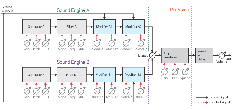
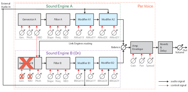
This allows you to route the signal from Generator A through all four Modifiers in series (see “Signal flow with the “Link Engines” function”).
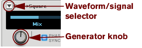
These include a number of carefully resynthesized and modeled instruments, plus 31 wave tables (see “Waveform/signal selector”).
Harmonic Stretch, Pitch Warp, Filter Curve, Pitch Curve and Partial Envelopes have been added (see “Modifier 1 and 2”).
|
•
|

|
•
|


|
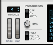
Set the desired Pitch Bend range for the “Pitch” wheel with the up/down buttons, or by click-holding on the display and dragging up/down.
|
The Pitch bend wheel can be used for bending note pitches up and down. Parsec 2 also responds to Pitch Bend MIDI data from a connected MIDI master keyboard. You set the desired Pitch bend Range with the “P. Range” control above the Pitch bend wheel.
#Mod
The Mod wheel can be used for controlling almost any parameter in Parsec 2. Use the Mod wheel as a Source parameter in the Modulation Bus section and then route to the desired Destination parameter(s), see “The Modulation Bus section”.
|
•
|
|
•
|
|
•
|

|
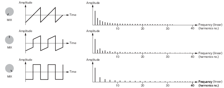
|
•
|
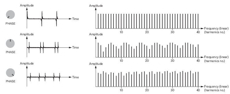
|
•
|
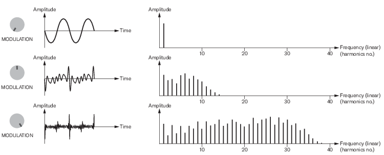
|
•
|
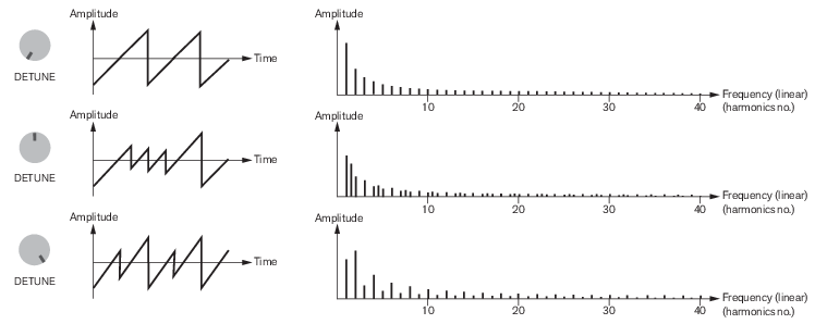

|
|
•
|
|
•
|
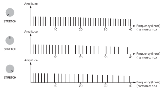
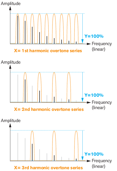
This signal consists of eight different harmonic overtone series, each containing 16 partials. The different harmonic overtone series can be accessed by turning the Generator knob. The transitions between the overtone series are smooth. The figure below shows three examples of how the overtone series could look in the frequency spectrum.
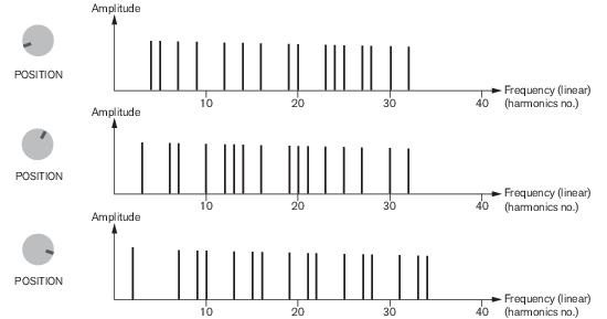
This signal consists of eight different inharmonic overtone series, each containing 16 partials. The different inharmonic overtone series can be accessed by turning the Generator (Position) knob. The transitions between the overtone series are continuous, i.e. the partials are individually transposed from one overtone series to another.
|
•
|
|
•
|
|
•
|
|
|
|
|
|
•
|
|
•
|
|
•
|
|
•
|
|
|
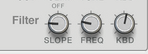
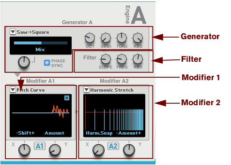
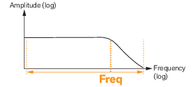
Each Sound Engine has one built-in combined “lowpass/high shelving” filter per voice, which can be used for shaping the Generator signals before being modified further by the Modifiers (see “Modifier 1 and 2”). The filter features the following parameters:
|
•
|

|
•
|
|
•
|
|
|
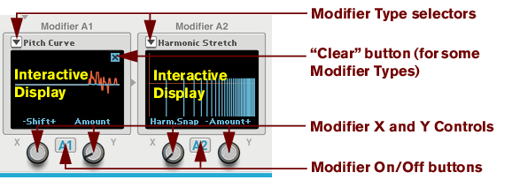
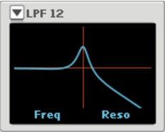
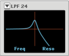
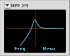
The two Modifiers in each Sound Engine control how the frequency content of the selected waveform/signal (see “Waveform/signal selector”) should be modified/affected. The modifiers are routed in series: Modifier 1 to Modifier 2.
|
•
|
|
•
|
|
|
|
•
|
|
|
|
•
|
|
|
|
•
|
|
|
|
|
|
|
|
|
|
|
|
•
|
|
|
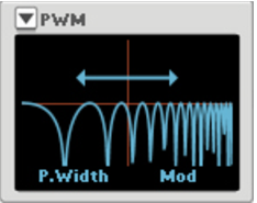
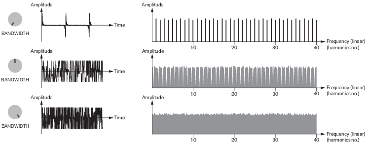
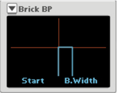
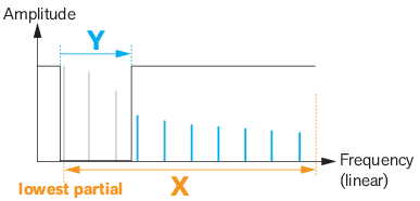
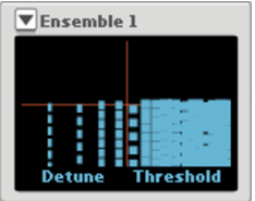
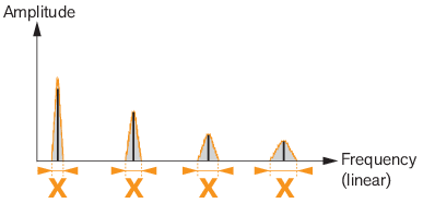
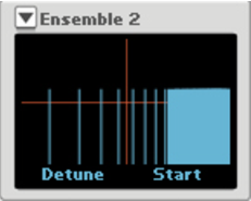
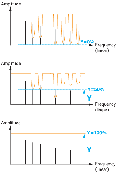
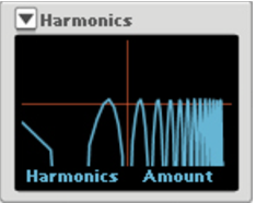
This simulates the frequency spectra you get from traditional pulse width modulation, i.e. when the pulse width of a square wave is constantly changed. Depending on what type of signal you have selected with the “Waveform/signal selector”, the character of the sound will be different. If you use a sawtooth signal the effect is almost the same as with traditional (square wave) pulse width modulation.
|
|

|
|
|
|
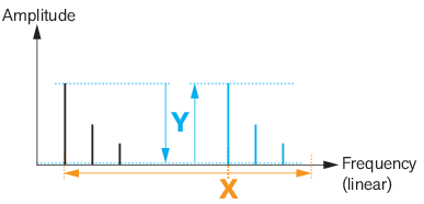
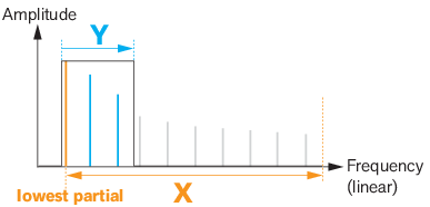
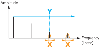
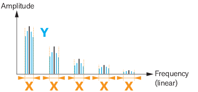
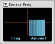
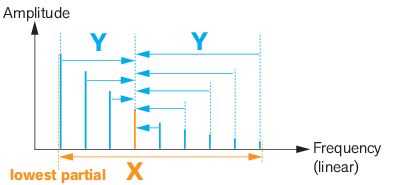
To create flageolet effects, raise the Y parameter fairly high and then assign the Y parameter as Destination to an Envelope Source in the Modulation Bus (see “The Modulation Bus section”). Set the modulation Amount to a low negative (-) value and adjust the Source Envelope Decay time to get the typical effect. Select the desired harmonic overtone series with the X knob.
|
|
|
|
•
|
|
|
|
•
|
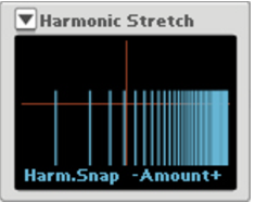
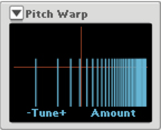
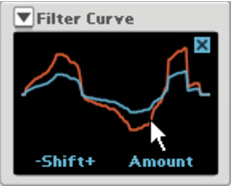
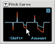
|
|
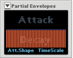
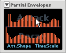

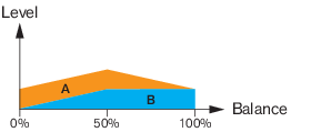
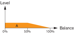
This allows you to use up to four Modifiers in series, to process the signal. See “Signal flow with the “Link Engines” function” for a signal flowchart and a description.
#Gain

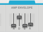
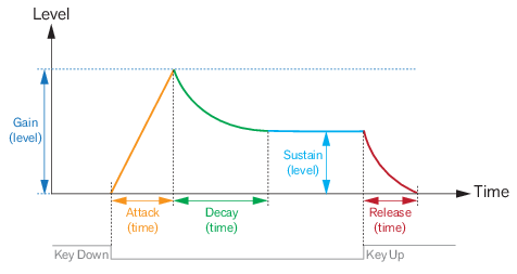
This is the maximum level the envelope will reach after the Attack stage is completed (see “Amp Envelope” below).
|
|
|
|
#Pan

|
|
|
•
|
|
•
|
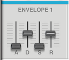
See “The Modulation Bus section” for details on how to assign Envelope 1 to the desired destination(s).
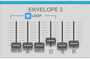
|
•
|
|
•
|
|
•
|
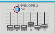
The modulation destination(s) for Envelope 2 can be assigned in the Modulation Bus, see “The Modulation Bus section”.
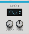
An LFO (Low Frequency Oscillator) is used for generating cyclic modulation. A typical example is to have an LFO modulate the pitch of a signal to produce vibrato, but there are countless other applications for LFOs. LFO 1 applies modulation polyphonically (one LFO per voice), i.e. if LFO 1 is assigned to modulate a parameter, an individual LFO will be started for each note you play. Also, LFO 1 always restarts on Note On (key down). Use the Modulation Bus to assign modulation destination(s) for LFO 1, see “The Modulation Bus section”.
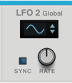
LFO 2 Global is monophonic and affects all voices together. Use the Modulation Bus to set modulation destination(s) for LFO 2, see “The Modulation Bus section”.
|
|
|
•
|
|
•
|
|
•
|
|
•
|
|
•
|
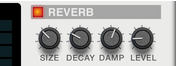
Use this parameter to adjust the balance between the unprocessed audio signal and the reverb effect.
|
•
|
|
•
|
|
•
|
|
•
|
|
•
|
|
|
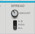
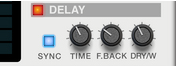
To get a wider stereo delay effect, turn up the Spread Amount knob, see “Spread”. This spreads the stereo input signals to the Delay and consequently gives a wider stereo effect from the Delay.
|
|
|
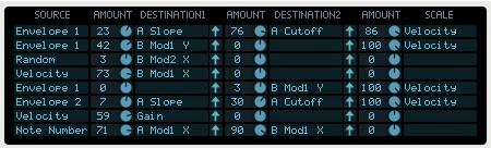
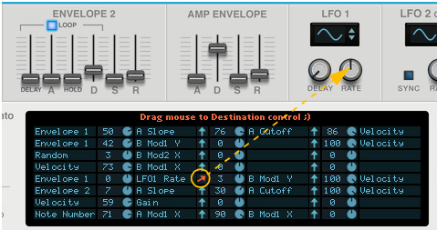
The available Scale parameters are the same as the Source parameters, see “Modulation Bus Source parameters.”.
|
|

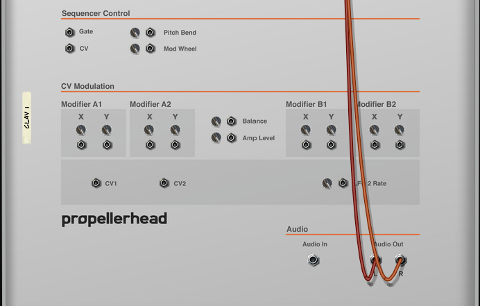
These control voltage (CV) inputs (with associated trim pots in some cases) can modulate the X and Y parameters of the Modifiers of the two Sound Engines. There are also inputs for modulating the global parameters Amp Level, LFO 2 Rate and Balance - plus two assignable CV inputs which can be used for modulating assigned Destination parameters in the Modulation Bus section, see “The Modulation Bus section”.