Now, you could drag the mouse pointer to an input jack, to connect the signal source to the destination. This is described in detail in “Connecting modules in “cable mode””.
|
•
|
Since you cannot connect cables straight from the front panel of Complex-1 to jacks on the rear panels of devices in the Reason rack, there is a set of jacks on the rear panel of Complex-1 for this purpose (see “Rear panel connections”).
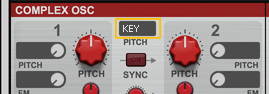
The Key 1 and Key 2 outputs described below can also send out pitch bend control signals if desired.
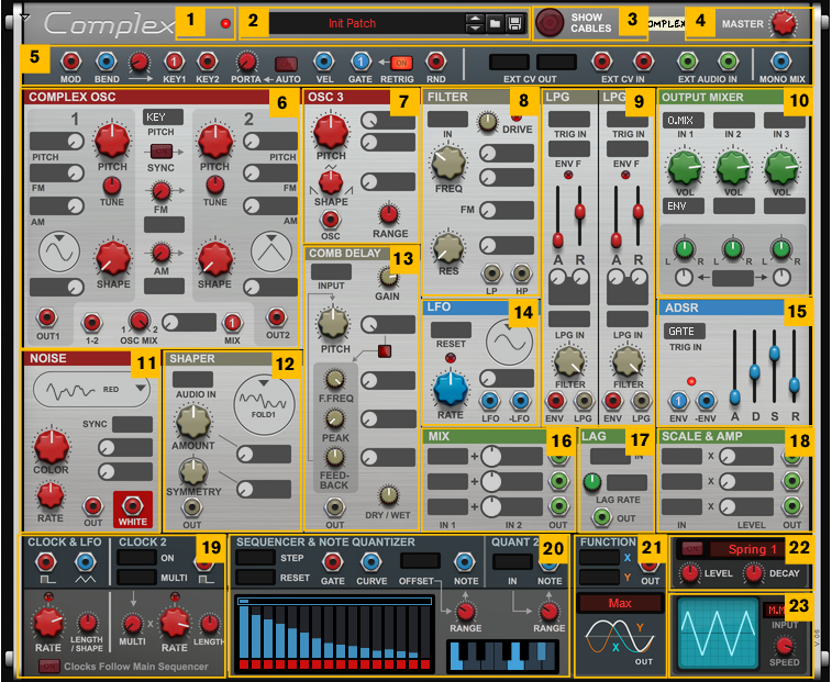
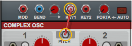
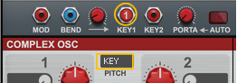
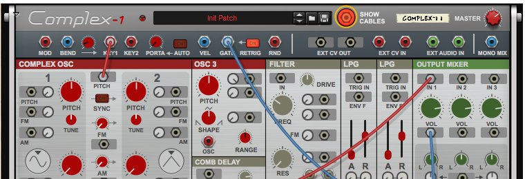
The Key 1 output sends out a pitch signal which corresponds to the last played note on your MIDI keyboard/On-screen Piano Keys. For example, connecting the Key 1 output to the pitch input on an oscillator module makes it possible to control the oscillator pitch from a MIDI keyboard. Besides the note/pitch information the output can also send Pitch Bend information from your MIDI keyboard, according to the range you have defined with the Bend to Key knob, see “Bend to Key range”.
If connected, the Key 2 output sends out a second pitch signal allowing you to play duophonic/paraphonic on your MIDI keyboard/On-screen Piano Keys - if you connect the Key 2 output to a second oscillator or similar. Besides the note/pitch information the output also sends any Pitch Bend information from your MIDI keyboard, according to the range you have defined with the Bend to Key knob, see “Bend to Key range”. The Pitch Bend signal is the same as for the Key 1 output.
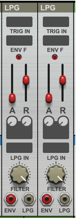
This output sends out a control signal based on the last Keyboard Velocity value sent from your MIDI keyboard/On-screen Piano Keys. A typical example would be to connect the Vel output to a Frequency modulation input on a Filter module or similar. See “Making the LPG module velocity sensitive” for another example.
#Tune
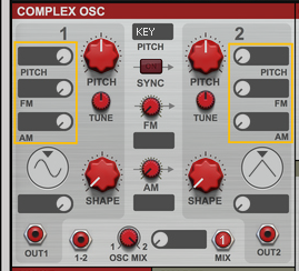
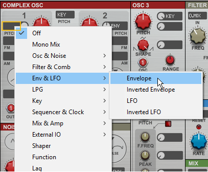
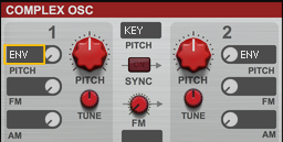
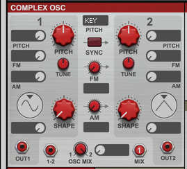
Besides the Shape Modulation (see “Waveform selector, Shape knob and Shape Modulation”), there are three Oscillator Modulation inputs, with associated attenuation knobs, for each oscillator. The modulation destinations are as follows:
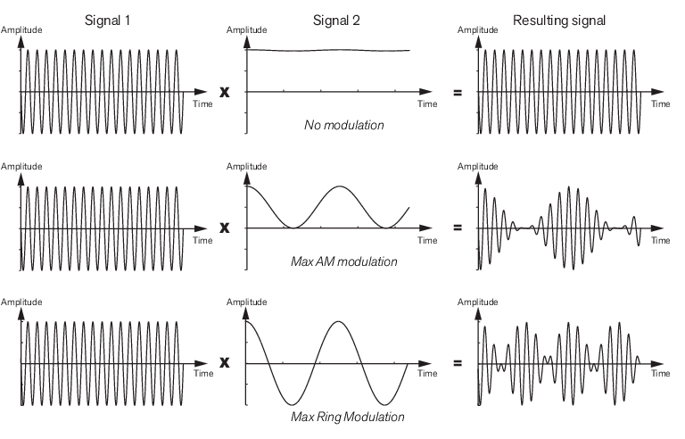
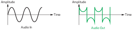
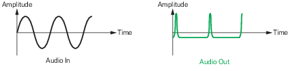
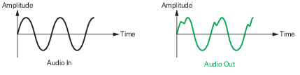
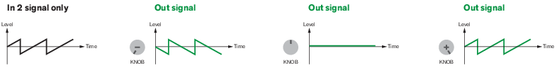
Here you can amplitude modulate the oscillator signal. starting with amplitude modulation up to 50% (12 o’clock position) and then continues with ring modulation from 50% and above. For more details about amplitude modulation, see “AM (amplitude modulation)”.
|
•
|

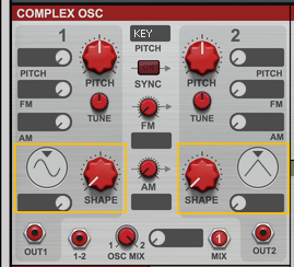
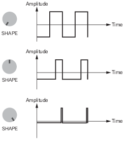
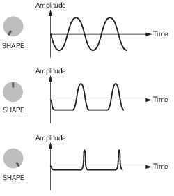
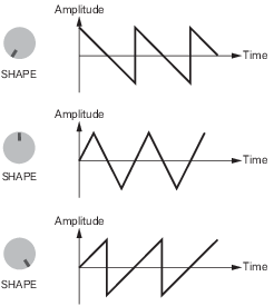
Here you can modulate the Shape control for the currently selected waveform (see “Waveform selector, Shape knob and Shape Modulation” for more details about the waveforms).
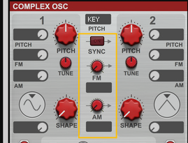
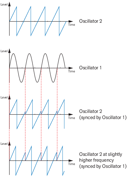
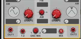
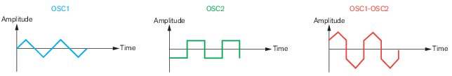
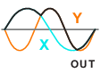
Besides the individual oscillator modulation possibilities (see “Pitch, FM and AM Modulation inputs”), you can also modulate Oscillator 2 from Oscillator 1 in a number of different ways:
|
•
|
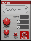
#Type
|
•
|
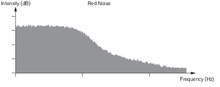
With Color (see “Color”) and Rate set to max (see “Rate”) this produces a noise that has more energy at lower frequencies and has a power drop of approximately -12 dB/oct. Red noise is also known as Brownian Noise. Here the “Color” knob controls a lowpass filter.
|
•
|
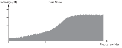
With Color (see “Color”) and Rate set to max (see “Rate”) this produces a noise that has low energy at lower frequencies and increases in power by approximately +12 dB/oct. Here the “Color” knob controls a highpass filter.
|
•
|
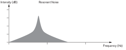
This generates a resonant band pass filtered noise. The Color knob (see “Color”) controls the center frequency - or pitch if you will - and the Rate knob (see “Rate”) controls the bandwidth of the resonant band. With “Rate” set to zero the band is narrow with little “side noise”.
|
•
|
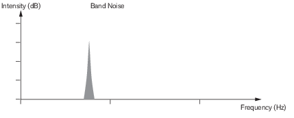
The Band noise is similar to the Resonant noise described above, but more narrow, with even less “side noise”. The Color knob (see “Color”) controls the center frequency - or pitch if you will - and the Rate knob (see “Rate”) controls the width of the noise band. With “Rate” set to zero the band is narrow almost no “side noise” at all.
|
•
|
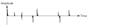
As the name implies, this can generate the sound of static interference (pops and clicks) if you use low Rate (see “Rate”) settings. The Color knob (see “Color”) controls the cutoff frequency of a low pass filter and the Rate knob (see “Rate”) controls the density, i.e. the amount of noise bursts. High “Rate” settings generates more compact noise.
|
•
|
This generates random series of 1 and 0 - in practice a type of raw aliasing square/pulse wave. The Color knob (see “Color”) controls the pitch - and the Rate knob (see “Rate”) controls the density of the on/off bursts. With “Rate” set to zero the pitch is steady.
|
•
|
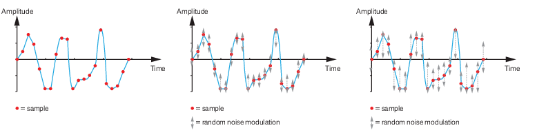
This algorithm produces a range of noises, from tonal up to almost white noise, by individually amplitude modulating each sample in a randomly generated wave table with noise. At low Rate settings (see “Rate”) there is no modulation, which results in a cleaner “steady” tone. At higher Rate settings, more noise modulation is introduced, which results in a more “noisy” signal. The Color knob (see “Color”) controls the pitch.
The parameter has different character depending on the selected noise Type. For more details, see “Type” above.
#Rate
The parameter produces different character depending on the selected noise Type. For more details, see “Type” above.
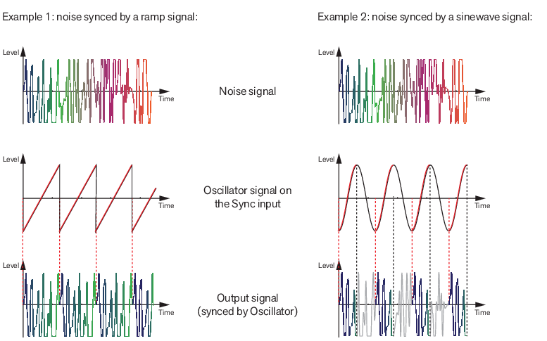
#Sync
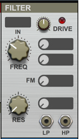
#Freq
#Res
|
•
|
#FM
|
•
|
|
•
|
|
•
|
|
•
|
|
•
|
|
•
|
#Out
|
|
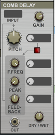
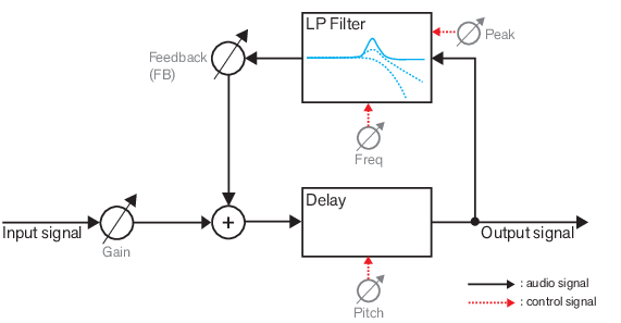
#Gain
|
|
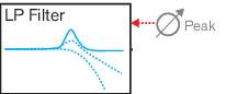
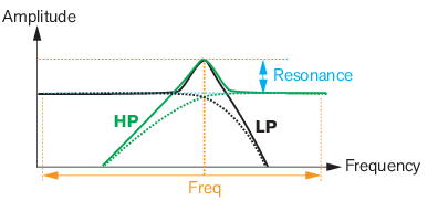
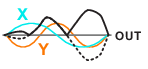
Filter character at low and medium Peak values (dotted lines) and at high Peak values (filled line).
|
|
|
|
|
|
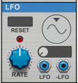
When reset from a bipolar signal source the LFO cycle will restart according to the general descriptions in “About Trig/Gate and Reset inputs”.
|
|
|
|
#In 1
#In 2
#Out
#In
#Out
|
|
#In
#Out
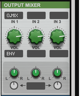
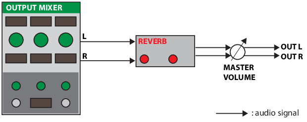
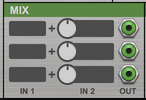
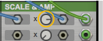
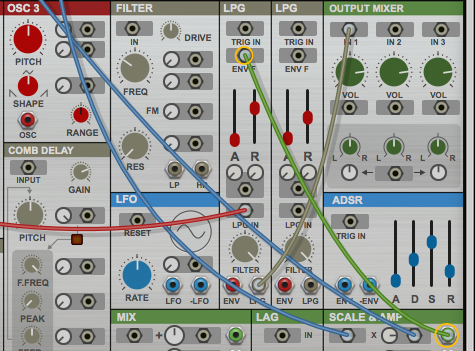
The Output Mixer module features three channels with their own built-in amplifiers. Each channel can have its own Pan position - and the Pan positions can also be modulated from an external modulation source. The mixed signal output is internally routed to the inputs of the Reverb module, see “The Reverb module”.
#Pan
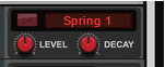
The Reverb module can be used as a “master insert effect” for adding reverb to the Complex-1 output signal. The audio input to the Reverb module is internally routed from the Mixer module outputs (see “The Output Mixer module”) and the output is internally routed to the Master L&R Outs, via the Master Level control.
|
•
|
|
•
|
|
•
|
|
•
|
#Out
#Wave
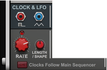
#Rate
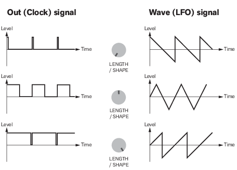
Here you can set the pulse width of the unipolar Clock signal (which is output on the Out jack, see “Out”) and the shape of the LFO signal (which is output on the Wave output, see “Wave”).
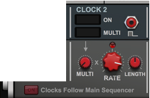
#On
If modulated from a bipolar signal source the Clock is activated as described in “About Trig/Gate and Reset inputs”.
|
|
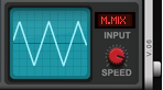
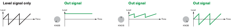
Select a modulation source for the “Multi knob”, if desired.
|
#Out
#Rate
Here you can set the pulse width of the Clock 2 signal (that is output on the Out jack, see “Out”). The pulsewidth characteristics is the same as for Clock 1, see “Length/Shape”.
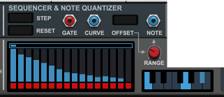
#Step
When modulated from a bipolar signal source the sequencer will advance one step for every trig pulse as described in “About Trig/Gate and Reset inputs”.
When modulated from a bipolar signal source the sequencer will be restarted with every new trig pulse as described in “About Trig/Gate and Reset inputs”.
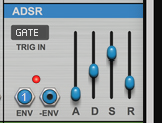
#Gate
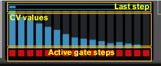
This outputs the clock gate/pulse signals from the sequencer - as defined by the red “boxes” in the Sequencer display (see “Sequencer display”).
#Note
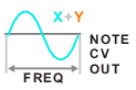
This outputs the sequencer Curve+Offset signal as a continuous CV signal, quantized to the specific note values you have set up in the Keyboard display (see “Keyboard display”).
|
•
|
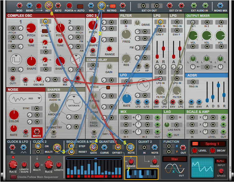
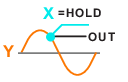
Connect the Gate output to the Clock 2 On input (1) to start the Clock 2 when you play and hold a note.
|
|
•
|
Also connect the Gate output to the Sequencer Reset input (2) to restart the sequence when you play a new note.
|
|
•
|
Connect the Sequencer Gate output to the LPG Trig In (4) so that the LPG is triggered on every Sequencer Gate
signal. |
|
•
|
Connect the Key output to the Sequencer Offset input (6) so you can transpose the sequence from your MIDI
keyboard. |
|
•
|
If desired, click some notes in the Keyboard display (7) (to define what notes should play back) and turn up the Range knob above the Keyboard display to set the total note range to be played back.
|

The Quant 2 module is kind of an “extension” to the Sequencer and Note Quantizer module, which you can use for quantizing a CV input signal to the notes you have selected in the keyboard display (see “Keyboard display”) in the Sequencer and Note Quantizer module.
#In
#Note
This outputs a continuous CV signal, quantized to the specific note values you have set up in the Keyboard display (see “Keyboard display”).
#Out
|
•
|

|
•
|
|
•
|
|
•
|
|
•
|
|
•
|
|
|
See “About Trig/Gate and Reset inputs” for more details regarding trig signals.
|
|
•
|

|
•
|
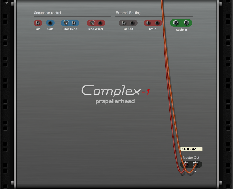
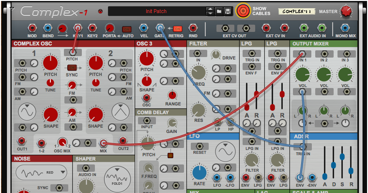
These control voltage (CV) inputs and outputs can be used for modulation. The signals on the inputs and outputs are then available in the Performance section on the front panel, see “Ext CV In 1&2” and “Ext CV Out 1&2”.
Here you can route external audio signals into Complex-1. The signals on these inputs are then available on the Audio Inputs in the Performance section on the front panel, see “Ext Audio In 1&2”.
These are the main audio outputs. When you create a new Complex-1 device, these outputs are auto-routed to the first available Mix Channel in the main mixer. If there is no Mix Channel available, a new one will be automatically created.

|
2.
|
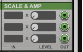
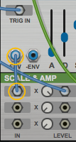
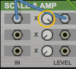
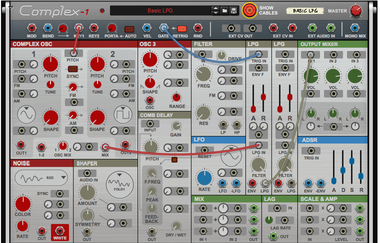
Reroute the Gate output in the Performance section from the LPG Trig In to the IN 1 input on the Scale & Amp
module (1). Then, patch a cable from the VEL output in the Performance section to the Level 1 input on the Scale & Amp module (2): |
|
2.
|
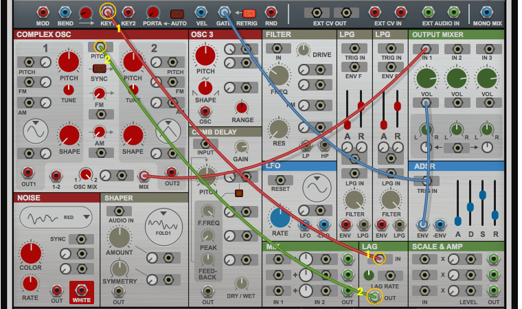
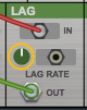
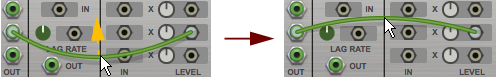
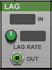
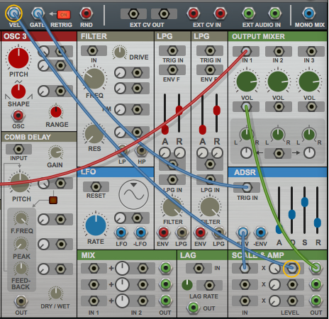
Reroute the Key1 output in the Performance section from the Pitch input of the Complex Oscillator to the IN jack of the Lag module (1). Then, route the OUT jack of the Lag module back to the Pitch input of the Complex Oscillator (2):
|